 |
 |
 |
 |
 |
 |
 |
 |
 |
 |
 |
  |
 |
||||||||||||
 |
|
|
|
 |
  Advanced Character Physics Advanced Character Physics[ August 31, 2005 ] by Thomas Jakobsen This article explains the basic elements of an approach to physically-based modeling, which allows simulation of cloth, soft and rigid bodies and even articulated or constrained bodies using both forward and inverse kinematics. |
||||||||||||||||||||||||||
continues from page 1 5. Rigid bodies The equations governing motion of rigid bodies were discovered long before the invention of modern computers. To be able to say anything useful at that time, mathematicians needed the ability to manipulate expressions symbolically. In the theory of rigid bodies, this lead to useful notions and tools such as inertia tensors, angular momentum, torque, quaternions for representing orientations etc. However, with the current ability to process huge amounts of data numerically, it has become feasible and in some cases even advantageous to break down calculations to simpler elements when running a simulation. In the case of 3D rigid bodies, this could mean modeling a rigid body by four particles and six constraints (giving the correct amount of degrees of freedom, 4x3-6 = 6). This simplifies a lot of aspects and it’s exactly what we will do in the following. Consider a tetrahedron and place a particle at each of the four vertices. In addition, for each of the six edges on the tetrahedron create a distance constraint like the stick constraint discussed in the previous section. This is actually enough to simulate a rigid body. The tetrahedron can be let loose inside the cube world from earlier and the Verlet integrator will let it move correctly. The function SatisfyConstraints() should take care of two things: 1) That particles are kept inside the cube (like previously), and 2) That the six distance constraints are satisfied. Again, this can be done using the relaxation approach; 3 or 4 iterations should be enough with optional square root approximation. Now clearly, in general rigid bodies do not behave like tetrahedrons collision-wise (although they might do so kinetically). There is also another problem: Presently, collision detection between the rigid body and the world exterior is on a vertex-only basis, that is, if a vertex is found to be outside the world it is projected inside again. This works fine as long as the inside of the world is convex. If the world were non-convex then the tetrahedron and the world exterior could actually penetrate each other without any of the tetrahedron vertices being in an illegal region (see Figure 3 where the triangle represents the 2D analogue of the tetrahedron). This problem is handled in the following.
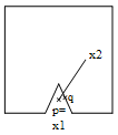
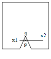
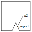
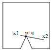
Figure 3. A tetrahedron penetrating the world. We’ll first consider a simpler version of the problem. Consider the stick example from earlier and assume that the world exterior has a small bump on it. The stick can now penetrate the world exterior without any of the two stick particles leaving the world (see Figure 4). We won’t go into the intricacies of constructing a collision detection engine since this is a science in itself. Instead we assume that there is a subsystem available which allows us to detect the collision. Furthermore we assume that the subsystem can reveal to us the penetration depth and identify the penetration points on each of the two colliding objects. (One definition of penetration points and penetration depth goes like this: The penetration distance d p is the shortest distance that would prevent the two objects from penetrating if one were to translate one of the objects by the distance d p in a suitable direction. The penetration points are the points on each object that just exactly touch the other object after the aforementioned translation has taken place.) Take a look again at Figure 4. Here the stick has moved through the bump after the Verlet step. The collision engine has identified the two points of penetration, p and q. In Figure 4a, p is actually identical to the position of particle 1, i.e., p=x1. In Figure 4b, p lies between x1 and x2 at a position ¼ of the stick length from x1. In both cases, the point p lies on the stick and consequently it can be expressed as a linear combination of x1 and x2, p=c1 x1+c2 x2 such that c1+c2=1. In the first case, c1=1 and c2=0, in the second case, c1=0.75 and c2=0.25. These values tell us how much we should move the corresponding particles.
To fix the invalid configuration of the stick, it should be moved upwards somehow. Our goal is to avoid penetration by moving p to the same position as q. We do this by adjusting the positions of the two particles x1 and x2 in the direction of the vector between p and q, Δ =q-p. In the first case, we simply project x1 out of the invalid region like earlier (in the direction of q) and that’s it (x2 is not touched). In the second case, p is still nearest to x1 and one might reason that consequently x1 should be moved more than x2. Actually, since p=0.75 x1 + 0.25 x2, we will choose to move x1 by an amount of 0.75 each time we move x2 by an amount of 0.25. In other words, the new particle positions x1’ and x2’ are given by the expressions:
where λ is some unknown value. The new position of p after moving both particles is p’=c1 x1’+ c2 x2’. Recall that we want p’=q, i.e., we should choose λ exactly such that p’ ends up coinciding with q. Since we move the particles only in the direction of Δ, also p moves in the direction of Δ and consequently the solution to the equation p’=q can be found by solvingp'·Δ = q·Δ (**) for λ. Expanding the left-hand side yields:
which together with the right-hand side of (**) gives:
Plugging λ into (*) gives us the new positions of the particles for which p’ coincide with q. Figure 5 shows the situation after moving the particles. We have no object penetration but now the stick length constraint has been violated. To fix this, we do yet another iteration of the relaxation loop (or several) and we’re finished.
The above strategy also works for the tetrahedron in a completely analogous fashion. First the penetration points p and q are found (they may also be points interior to a triangle), and p is expressed as a linear combination of the four particles p=c1 x1+c2 x2+c3 x3+c4 x4 such that c1+c2+c3+c4=1 (this calls for solving a small system of linear equations). After finding Δ =q-p, one computes the value:
and the new positions are then given by: x1' = x1 + c1·λ·Δ Here, we have collided a single rigid body with an immovable world. The above method generalizes to handle collisions of several rigid bodies. The collisions are processed for one pair of bodies at a time. Instead of moving only p, in this case both p and q are moved towards each other. Again, after adjusting the particle positions such that they satisfy the non-penetration constraints, the six distance constraints that make up the rigid body should be taken care of and so on. With this method, the tetrahedron can even be imbedded inside another object that can be used instead of the tetrahedron itself to handle collisions. In Figure 6, the tetrahedron is embedded inside a cube.
Figure 6. Embedding the tetrahedron inside another object. First, the cube needs to be ‘fastened’ to the tetrahedron in some way. One approach would be choosing the system mass midpoint 0.25*(x1+x2+x3+x4) as the cube’s position and then derive an orientation matrix by examining the current positions of the particles. When a collision/penetration is found, the collision point p (which in this case will be placed on the cube) is then treated exactly as above and the positions of the particles are updated accordingly. As an optimization, it is possible to precompute the values of c1-c4 for all vertices of the cube. If the penetration point p is a vertex, the values for c1-c4 can be looked up and used directly. Otherwise, p lies on the interior of a surface triangle or one of its edges and the values of c1-c4 can then be interpolated from the precomputed values of the corresponding triangle vertices. Usually, 3 to 4 relaxation iterations are enough. The bodies will not behave as if they were completely rigid since the relaxation iterations are stopped prematurely. This is mostly a nice feature, actually, as there is no such thing as perfectly rigid bodies – especially not human bodies. It also makes the system more stable. By rearranging the positions of the particles that make up the tetrahedron, the physical properties can be changed accordingly (mathematically, the inertia tensor changes as the positions and masses of the particles are changed). Other arrangements of particles and constraints than a tetrahedron are possible such as placing the particles in the pattern of a coordinate system basis, i.e. at (0,0,0), (1,0,0), (0,1,0), (0,0,1). Let a, b, and c be the vectors from particle 1 to particles 2, 3, and 4, respectively. Constrain the particles’ positions by requiring vectors a, b, and c to have length 1 and the angle between each of the three pairs of vectors to be 90 degrees (the corresponding dot products should be zero). (Notice, that this again gives four particles and six constraints.) It is possible to connect multiple rigid bodies by hinges, pin joints, and so on. Simply let two rigid bodies share a particle, and they will be connected by a pin joint. Share two particles, and they are connected by a hinge. See Figure 7.
It is also possible to connect two rigid bodies by a stick constraint or any other kind of constraint – to do this, one simply adds the corresponding ‘fix-up’ code to the relaxation loop. This approach makes it possible to construct a complete model of an articulated human body. For additional realism, various angular constraints will have to be implemented as well. There are different ways to accomplish this. A simple way is using stick constraints that are only enforced if the distance between two particles falls below some threshold (mathematically, we have a unilateral (inequality) distance constraint, |x2-x1|>100). As a direct result, the two particles will never come too close to each other. See Figure 8.
Another method for restraining angles is to satisfy a dot product constraint: (x2 - x0)·(x1 - x0) < α Particles can also be restricted to move, for example, in certain planes only. Once again, particles with positions not satisfying the above-mentioned constraints should be moved – deciding exactly how is slightly more complicated that with the stick constraints. Actually, in Hitman corpses aren’t composed of rigid bodies modeled by tetrahedrons. They are simpler yet, as they consist of particles connected by stick constraints in effect forming stick figures. See Figure 9. The position and orientation for each limb (a vector and a matrix) are then derived for rendering purposes from the particle positions using various cross products and vector normalizations (making certain that knees and elbows bend naturally).
Figure 9. The particle/stick configuration used in Hitman for representing the human anatomy. In other words, seen isolated each limb is not a rigid body with the usual 6 degrees of freedom. This means that physically the rotation around the length axis of a limb is not simulated. Instead, the skeletal animation system used to setup the polygonal mesh of the character is forced to orientate the leg, for instance, such that the knee appears to bend naturally. Since rotation of legs and arms around the length axis does not comprise the essential motion of a falling human body, this works out okay and actually optimizes speed by a great Angular constraints are implemented to enforce limitations of the human anatomy. Simple self collision is taken care of by strategically introducing inequality distance constraints as discussed above, for example between the two knees – making sure that the legs never cross. For collision with the environment, which consists of triangles, each stick is modeled as a capped cylinder. Somewhere in the collision system, a subroutine handles collisions between capped cylinders and triangles. When a collision is found, the penetration depth and points are extracted, and the collision is then handled for the offending stick in question exactly as described in the beginning of Section 5. Naturally, a lot of additional tweaking was necessary to get the result just right.
This section contains various remarks that didn’t fit anywhere else. MOTION CONTROL To influence the motion of a simulated object, one simply moves the particles correspondingly. If a person is hit at the shoulder, move the shoulder particle backwards over a distance proportional to the strength of the blow. The Verlet integrator will then automatically set the shoulder in motion. This also makes it easy for the simulation to ‘inherit’ velocities from an underlying traditional animation system. Simply record the positions of the particles for two frames and then give them to the Verlet integrator, which then automatically continues the motion. Bombs can be implemented by pushing each particle in the system away from the explosion over a distance inversely proportional to the square distance between the particle and the bomb center. It is possible to constrain a specific limb, say the hand, to a fixed position in space. In this way, one can implement inverse kinematics (IK): Inside the relaxation loop, keep setting the position of a specific particle (or several particles) to the position(s) wanted. Giving the particle infinite mass (invmass=0) helps making it immovable to the physics system. In Hitman, this strategy is used when dragging corpses; the hand (or neck or foot) of the corpse is constrained to follow the hand of the player. HANDLING FRICTION Friction has not been taken care of yet. This means that unless we do something more, particles will slide along the floor as if it were made of ice. According to the Coulomb friction model, friction force depends on the size of the normal force between the objects in contact. To implement this, we measure the penetration depth d p when a penetration has occurred (before projecting the penetration point out of the obstacle). After projecting the particle onto the surface, the tangential velocity v t is then reduced by an amount proportional to d p (the proportion factor being the friction constant). This is done by appropriately modifying x*. See the Figure 10. Care should be taken that the tangential velocity does not reverse its direction – in this case one should simply be set it to zero since this indicates that the penetration point has seized to move tangentially. Other and better friction models than this could and should be implemented.
Figure 10. Collision handling with friction (projection and modification of tangential velocity). COLLISION DETECTION One of the bottlenecks in physics simulation as presented here lies in the collision detection, which is potentially performed several times inside the relaxation loop. It is possible, however, to iterate a different number of times over the various constraints and still obtain good results. In Hitman, the collision system works by culling all triangles inside the bounding box of the object simulated (this is done using a octtree approach). For each (static, background) triangle, a structure for fast collision queries against capped cylinders is then constructed and cached. This strategy gave quite a speed boost. To prevent objects that are moving really fast from passing through other obstacles (because of too large time steps), a simple test if performed. Imagine the line (or a capped cylinder of proper radius) beginning at the position of the object’s midpoint last frame and ending at the position of the object’s midpoint at the current frame. If this line hits anything, then the object position is set to the point of collision. Though this can theoretically give problems, in practice it works fine. Another collision ‘cheat’ is used for dead bodies. If the unusual thing happens that a fast moving limb ends up being placed with the ends of the capped cylinder on each side of a wall, the cylinder is projected to the side of the wall where the cylinder is connected to the torso. MISCELLANEOUS The number of relaxation iterations used in Hitman vary between 1 and 10 with the kind of object simulated. Although this is not enough to accurately solve the global system of constraints, it is sufficient to make motion seem natural. The nice thing about this scheme is that inaccuracies do not accumulate or persist visually in the system causing object drift or the like – in some sense the combination of projection and the Verlet scheme manages to distribute complex calculations over several frames (other schemes have to use further stabilization techniques, like Baumgarte stabilization). Fortunately, the inaccuracies are smallest or even nonexistent when there is little motion and greatest when there is heavy motion – this is nice since fast or complex motion somewhat masks small inaccuracies for the human eye. A kind of soft bodies can also be implemented by using ‘soft’ constraints, i.e., constraints that are allowed to have only a certain percentage of the deviation ‘repaired’ each frame (i.e., if the rest length of a stick between two particles is 100 but the actual distance is 60, the relaxation code could first set the distance to 80 instead of 100, next frame 90, 95, 97.5 etc.). As mentioned, we have purposefully refrained from using heavy mathematical notation in order to reach an audience with a broader background. This means that even though the methods presented are firmly based mathematically, their origins may appear somewhat vague or even magical. For the mathematically inclined, however, what we are doing is actually a sort of time-stepping approach to solving differential inclusions (a variant of differential equations) using a simple sort of interior-point algorithm (see [Stewart] where a similar approach is discussed). When trying to satisfy the constraints, we are actually projecting the system state onto the manifold described by the constraints. This, in turn, is done by solving a system of linear equations. The linear equations or code to solve the constraints can be obtained by deriving the Jacobian of the constraint functions. In this article, relaxation has been discussed as an implicit way of solving the system. Although we haven’t touched the subject here, it is sometimes useful to change the relaxation coefficient or even to use over-relaxation (see [Press] for an explanation). Since relaxation solvers sometimes converge slowly, one might also choose to explicitly construct the equation system and use other methods to solve it (for example a sparse matrix conjugate gradient descent solver with preconditioning using the results from the previous frame (thereby utilizing coherence)). Note that the Verlet integrator scheme exists in a number of variants, e.g., the Leapfrog integrator and the velocity Verlet integrator. Accuracy might be improved by using these. Singularities (divisions by zero usually brought about by coinciding particles) can be handled by slightly dislocating particles at random. As an optimization, bodies should time out when they have fallen to rest. To toy with the animation system for dead characters in Hitman: Codename 47, open the Hitman.ini file and add the two lines “enableconsole 1” and “consolecmd ip_debug 1” at the bottom. Pointing the cursor at an enemy and pressing shift+F9 will cause a small bomb to explode in his vicinity sending him flying. Press K to toggle free-cam mode (camera is controlled by cursor keys, shift, and ctrl). Note that since all operations basically take place on the particle level, the algorithms should be very suitable for vector processing (Playstation 2 for example).
This paper has described how a physics system was implemented in Hitman. The underlying philosophy of combining iterative methods with a stable integrator has proven to be successful and useful for implementation in computer games. Most notably, the unified particle-based framework, which handles both collisions and contact, and the ability to trade off speed vs. accuracy without accumulating visually obvious errors are powerful features. Naturally, there are still many specifics that can be improved upon. In particular, the tetrahedron model for rigid bodies needs some work. This is in the works. At IO Interactive, we have recently done some experiments with interactive water and gas simulation using the full Navier-Stokes equations. We are currently looking into applying techniques similar to the ones demonstrated in this paper in the hope to produce faster and more stable water simulation. 9. Acknowledgements The author wishes to thank Jeroen Wagenaar for fruitful discussions and the entire crew at IO Interactive for cooperation and for producing such a great working environment. Feedback and comments are very welcome at .
References [Baraff] [Mirtich] [Press] [Stewart] [Verlet] Witkin, Andrew and David Baraff, Physically Based Modeling: Principles and Practice, Siggraph ’97 course notes, 1997. http://www.cs.cmu.edu/~baraff/sigcourse/index.html |
||||||||||||||||||||||||||
   |
||||||||||||||||||||||||||
|


